 across the "other brand" with small needle holes, the installation would
be more difficult. You may place these over the existing black gauges
(preferred.)
across the "other brand" with small needle holes, the installation would
be more difficult. You may place these over the existing black gauges
(preferred.)
| Installing ElectroLuminescent "Indiglo" gauges in the early 90-94 Eclipse/Talon/Laser |
a Visual Frequently Asked Question document by Mark Miller from PhillyDSM.com
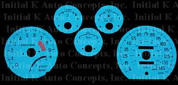
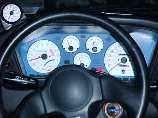
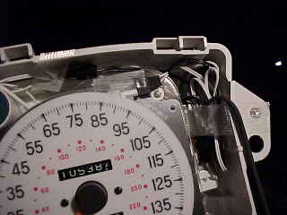
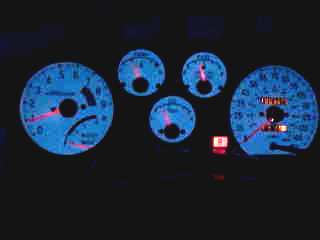
This is an interesting modification. Instead
of the stock black, we switch to white gauges. At night they glow
brilliantly blue/green. While purists may consider them "too ricey"
they do make it easier to see the gauges at night as well as improve contrast
during the day. The version used here by Initial
K Auto concepts has "large" needle holes that slip over the existing
gauges without needle removal. This brand also used the original artwork
from the American speedometer from the 1990 Diamond Star Motors triplets.
It uses odd numbers unlike the 91-94, although it still maintains the accuracy
and is compatible with the 90-94 cars. If you come
across the "other brand" with small needle holes, the installation would
be more difficult. You may place these over the existing black gauges
(preferred.)
This isn't difficult, but you need to allow
plenty of time [1-2 hours] wash hands frequently, and work on a padded
flat workspace. Do not try to upgrade the gauges sitting in the car. Take
the time to do it right the first time.
| Remove the front
instrument cluster frame by removing four Philip head trim screws from
under the ledge and under the two bottom corners, and those under the trim
on the right. Unplug the switches on the left. Place this part aside.
Remove the underlying instrument cluster by removing the screws on
each side then pulling out.
Pull the trip counter
knob out, and carefully remove the transparent protective cover, by pressing
the tabs and slowly working your way around the edge. Take your time.
|
 |
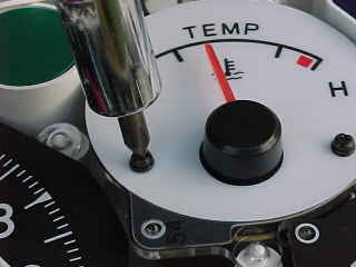
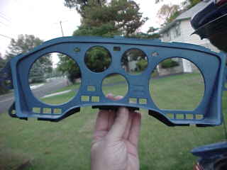
| Clean and wax the
outside of the cover (avoid fingerprints on the inside.) The black
mask layer is removed the same way ONCE A RETAINING SCREW IS REMOVED.
The
single screw is located on the rear printed circuit board between the "L"
on the oil gauge and the little turbo graphic icon on the stock boost gauge.
This part was painted blue in this series to match the car body color. Optional of course! Using a small Phillips screwdriver; and working on one gauge at a time (except oil --see note later) remove the two screws on the face of the gauge. |
 |
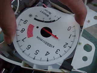
| Slightly bend the new gauge cover
and gently slip over the needle. Make sure the calibration holes
line up with the pins on the panel. Replace the face screws. Be extra careful
with the dual turbo/RPM gauge.
DO NOT over tighten the face screws as you will crush the illuminating structure of the material in those spots and could render the gauge unusable. |
 |
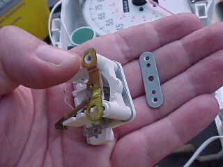
| The oil gauge must be removed from the cluster by removing the two retaining screws on the back (top middle in this photo) BEFORE you can remove the face screws. | 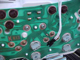 |
| Once you remove the oil gauge movement you can see that the face screws through it to a bar on the back. You will need to hold the movement together when you remove the face screws and the retaining bar on the back. [ If it falls apart, don't panic, it can be reassembled by placing the needle pivot into the jeweled receiver and the white plastic "arrow" slot over the magnetic coil movement. You may have to remove the needle --just pulls apart to reassemble] | 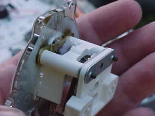 |
| Add the new gauge cover to the oil gauge movement; replace the face screws and the rear bar; then remount the movement into the cluster and replace the two screws on the back circuit board. | 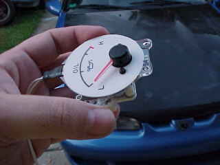 |
| The power wires from each gauge should
be routed away from all moving parts and where they will not be seen when
the black plastic mask is replaced. I found it best to route all wires
to the top right corner.
Plug them into the power supply cable and check that each connector snaps firmly in place. Make sure the wire to pin interface in the connector is tight, too. This might be a good time to add power and check the connections. Although the mask will hold the new illuminated gauge covers on, it might be good to add tiny pieces of clear tape on any edge that sticks up. Do not glue anything, the best mods are reversible. |
 |
| Secure the extra wire with nylon tie wraps
or electrical tape in otherwise empty areas behind the gauges.
You will need to route the single power cable out to the remote power supply next. |
 |
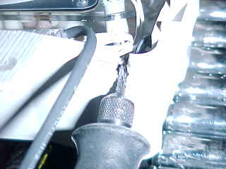
| I used my handy
cordless Dremel to carve a small slot in the top right corner for the
power cable (to the left of the Dremel
in
this photo.)
Note: Blow out ALL the bits of plastic or they may migrate to the inside of the transparent cover and annoy you later! |
 |
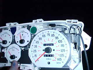
| Snap on the black plastic mask by inserting
the tabs and carefully squeezing together.
Make sure everything is clean, needles
are in the approx. right place, no wires are showing, then snap the (cleaned)
clear cover back on.
I wedged the epoxy
power supply box into the wire harness to the right of the opening
behind the vents. You do not want it to rattle later. Nylon tie wraps
are useful here, too.
|
 |
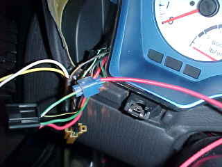
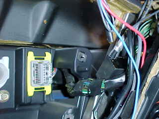
| We need to supply a good ground (12 volts neg.) to the black wire on the power supply. I used the 10 mm bolt under the speedometer cable ...just loosened it a bit, slipped a crimped spade connector under, then retightened it. See the blue wire in this photo. You can use any grounded bolt you prefer. | 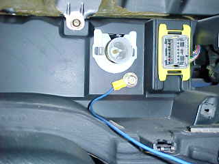 |
| The illuminated gauges need a source of
12 positive power (to the red wire on the supply box) whenever the lights
are on. You CAN NOT use the stock dimmer for this supply.
It is not recommended to illuminate the gauges all the time either (i.e. do not hook up the ignition positive) as they have a finite lifespan. A good source is the middle wire connected to the stock fog lamp switch on the left side of the cluster. See the blue vampire tap that is crimped on a red wire. If you don't have the stock fog switch, find a source in the lighting bundle under the steering column. An inline 2 amp fuse would be a good idea, but the fog circuit is fused as well. Note: crimp/vampire taps come in various sizes and while they may be suitable for gauge illumination, they are not reliable for important circuits like ECU connections, etc. Soldering and shrink wrap is preferred. |
 |
| I mounted the color switch/intensity control
panel to the existing trim screw that holds the padded frame around the
cluster (just above the ignition key) ... not seen in the photos but easy
to reach when needed.
Some versions have a "six color" self stick panel that needs to be applied. You shouldn't need to make any new holes. Make sure everything works; plug in the dimmer, fog, etc. and replace the front padded panel frame. Replace the trip counter knob by pressing it in. |
|
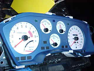
| If you keep the existing light bulbs you
will get orange needles on the blue/green background and the odometer will
be visible.
You can also remove the needles, scrape the orange paint off, and recolor with different color translucent ink (markers) but its tough to get something that looks good day and night. I think the stock needles look good on blue. |
 |
Other resources: ClubDSM.com PhillyDSM.com VFAQ.com
AMSOIL Synthetic Motor Oil Factory Direct 800-956-5695. Customer number: 531929 |

The World's largest tire retailer provides excellent service and great prices. Visit! |